Test runs, break-in, and validation of injection molding tools

An injection molding tool may be designed and manufactured with great care and still require adjustments before it is ready for production. This is not a sign of a flaw in the process. It is an expected part of the process.

Test runs, ramp-up, and validation are the three phases that bridge the gap between a finished tool and stable, reproducible production. Each phase has its own purpose, and they cannot be substituted for one another.

Skipping these phases or rushing through them is one of the most common reasons why production start-up is delayed or why quality issues aren’t detected until the parts are already in circulation. Read about how the process from idea to finished injection mold proceeds here

Test Run: First Items from the Tool

The test run is the first time that plastic material is injected into the new mold. The purpose is to produce a set of parts under controlled conditions and to systematically inspect the results.

A test run is not conducted under full production pressure. The process parameters are adjusted carefully, and time is taken to observe how the tool and the material behave.

The first parts are inspected for:
• Proper mold filling without short shots or flash
• Dimensions compared to the technical specification
• Surface quality and finish
• Presence of weld seams, sink marks, or air pockets
• Ejection process without marks or deformations on the part
• Stable cycle time

The results of the test run form the basis for the break-in phase. Deviations are systematically recorded and prioritized based on their impact on the part’s function and appearance.

Commissioning: Tool and Process Adjustment

The commissioning phase is the iterative phase during which the deviations identified during the test run are addressed. This may involve adjustments to both the process parameters and the tool itself.

Process adjustments involve optimizing injection pressure, temperature, cycle time, and cooling time so that the material behaves as expected in the specific mold.

In most cases, a hot runner system is used, and the commissioning process therefore also includes adjusting the hot runner system. This involves calibrating zone temperatures, checking for balanced filling across cavities, and ensuring that the gates open and close correctly. A properly calibrated hot runner system is essential for stable production and consistent part quality.

Mechanical adjustments to the mold may include:
• Polishing or modifying mold cavities to correct surface defects
• Widening or narrowing gates to influence the filling pattern
• Adjusting vents to eliminate air entrapments
• Adjusting the ejector system to prevent marks on the part
• Correcting dimensions that fall outside the tolerance

The ramp-up phase requires close collaboration between the mold maker and the plastics engineer, as solutions on the process side and the mold side influence one another. For example, a change in injection pressure may solve a filling problem but create new stress on a weak part of the mold. Read more about the process in this article: Design for Manufacturing in Injection Molding Tools

Validation: Formal Documentation of Process Capability

Validation is the formal conclusion of the ramp-up phase. It documents that the tool and process, when used together, can consistently and reproducibly produce parts that meet the specifications.
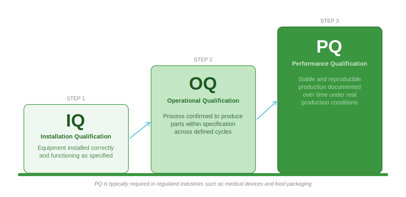
Validation is typically carried out in two steps:

  1. IQ (Installation Qualification) confirms that the tool has been installed correctly and that all equipment is functioning as intended.
  2. OQ (Operational Qualification) confirms that the process can produce parts that meet the specification over a defined number of cycles and under varying but realistic process conditions.

In regulated industries such as medical devices and food packaging, a third step— PQ (Performance Qualification)—is typically added to document stable production over time and under actual production conditions.

Validation is not merely an internal quality control measure. It serves as documentation for the customer and, where applicable, for regulatory authorities, that the production process is under control.
What Concludes a Validation

A validation is complete when the measurement results from a defined number of produced parts confirm that all critical dimensions and properties are consistently within the specified tolerances.

This usually involves a statistical analysis of measurement data, not just an assessment of average values. Process capability indices such as Cp and Cpk are used to describe the margin between the process and the tolerance limits.

The result of the validation is a report that documents the process parameters, the measurement results, and the conclusion that the part is ready for mass production.

The Relationship Between Maintenance and Service Life

The process parameters established during commissioning and validation serve as a reference for the tool’s entire production life. Deviations from these parameters during routine operation are an early indication of wear or the need for maintenance.

A thoroughly validated and documented process therefore not only ensures a smooth start to production. It also provides an important basis for comparison to identify when a mold begins to deviate from its optimal condition. You can read more about this in these articles: Preventive Maintenance of Injection Molding Tools and What Determines the Service Life of an Injection Molding Tool?

Summary

Test runs, commissioning, and validation are three distinct phases, each with its own purpose. Test runs identify issues, commissioning resolves them, and validation documents the results.

The quality of these phases determines whether a production launch proceeds as expected and whether the documentation required in regulated industries or for supplier approval is available.

A tool is not ready for production until validation is complete and the documentation is in place.

Steel Grades for Injection Molding Tools – Selection of Tool Steel

Steel Grades for Injection Molding Tools – Selection of Tool Steel

The choice of steel for an injection molding mold is one of the decisions that has the greatest impact on the mold’s service life, maintenance requirements, and ability to deliver consistent part quality over time.

Nevertheless, in many projects, the choice of steel is treated as a technical detail left to the toolmaker, rather than as a strategic decision that should be made based on a concrete understanding of the production requirements.

This article reviews the most commonly used types of steel for injection molding tools, how they differ, and the factors that should guide the selection for a specific project.

Why the choice of steel is crucial

An injection molding mold is subjected to repeated thermal and mechanical stresses in every single cycle. The plastic material is injected under high pressure, cools and shrinks, and the part is ejected. This process is repeated hundreds of thousands or millions of times over the mold’s service life.

The steel must withstand these loads without deforming, cracking, or wearing to a degree that affects the quality of the workpiece. At the same time, it must be machinable to the required tolerances, polishable to the desired surface finish, and, in many cases, hardenable to increase its wear resistance.

The right steel is the one that best balances these requirements in relation to the specific project’s volume, material, and tolerance requirements. You can read more about how much an injection molding tool might cost here.

The Most Commonly Used Types of Steel

Pre-hardened steel

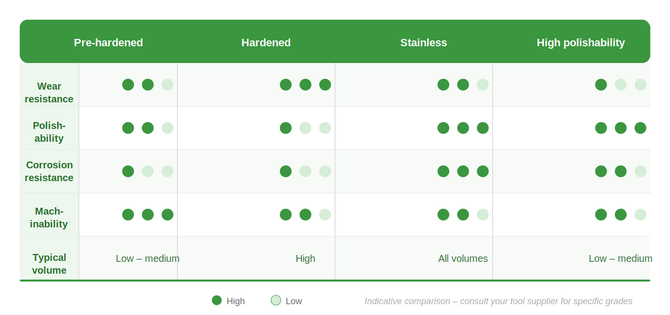
Pre-hardened steel is supplied in a pre-hardened condition and does not require further heat treatment after machining. It is the most commonly used grade for injection molding tools in standard- and medium-volume production.

Steels in this category are well-suited for mold cavities and cores, are easy to machine, and offer good polishability. They are not suitable for highly abrasive materials or extremely high production volumes, but cover a wide range of applications. Typical designations include P20 and 718—or supplier-specific variants such as Impax Supreme and Holdax from Uddeholm, which have comparable properties.

Hardened steel

Hardened steel achieves its final hardness through heat treatment after machining. This provides significantly higher wear resistance and makes it well-suited for high-volume production and for machining abrasive materials such as glass-fiber-reinforced and mineral-filled plastics.

H13 is one of the most commonly used designations in this category and is known by product names such as Orvar Supreme from Uddeholm. It offers good toughness and heat resistance, making it well-suited for demanding production conditions involving high temperatures and long runs. For particularly abrasive materials and extremely high production volumes, powder metallurgical steels such as Vanadis 4 Extra and Unimax are also available, combining high hardness with good toughness.

Stainless steel

Stainless steel is primarily used in situations where corrosion resistance is a requirement. This is particularly true in the production of medical equipment, food packaging, and components made of PVC or other corrosive types of plastic.

Steels in this category, typically designated S136 or sold under product names such as Stavax ESR and Corrax from Uddeholm, combine good polishability with high corrosion resistance and are well-suited for mold cavities with high surface quality requirements. Corrax stands out as a pre-hardened stainless steel that does not require heat treatment, making it easier to machine and repair.

Steel with high polishability

For applications with particularly high requirements for mirror polishing—such as optical components or visible design surfaces—steel with an exceptionally high degree of purity is used. Polmax from Uddeholm is an example of a steel developed specifically for this application, where the purity of the steel melt is critical to the final polishing result.

Copper-alloy inserts

Copper-alloyed materials are not used as structural steel for entire mold halves, but rather as inserts in areas with specific cooling requirements. They have a significantly higher thermal conductivity than steel and can be used to increase cooling efficiency in localized hot spots.

When manufacturing products for the food industry and medical devices, the choice of materials in these zones should always be verified against applicable regulatory requirements, as not all copper alloys are approved for contact with or proximity to food.

The factors that influence the choice

Production Volume

Expected lifetime volume is the most critical single factor. For prototype production and low-volume runs, a softer and less expensive steel may well suffice. For production runs in the millions, hardened steel is essential to avoid premature replacement of mold cavities and cores. You can read more about this in the article: What Determines the Service Life of an Injection Molding Tool?

Plastic material

Abrasive plastics such as glass-fiber-reinforced polyamide or mineral-filled PP wear down steel significantly faster than standard materials. These materials require higher hardness and wear resistance. Corrosive plastics such as PVC and POM require corrosion resistance. The article “From Idea to Finished Injection Mold” discusses this topic, among others.

Surface Requirements

Applications with high requirements for mirror polishing or textured finishes place special demands on steel quality and purity. Not all steel can be polished to optical quality—the purity of the steel melt is crucial here, and high-purity specialty steels are typically required.
Tolerance Requirements and Dimensional Stability Tight tolerances require steel with good dimensional stability during heat treatment. Certain types of steel deform more than others during hardening, which may require post-processing.

Refrigeration Requirements

In cases where standard cooling is insufficient and conformal cooling channels or local cooling inserts are required, the choice of material in those specific zones may differ from the rest of the mold.

Steel Selection and Maintenance

The choice of steel directly affects how easy and expensive it is to maintain a tool over time. Hardened steel is more wear-resistant, but more difficult and expensive to repair, as welding and finishing require more specialized work. Pre-hardened steel is easier to machine and repair, but wears out faster under demanding production conditions.

The choice is therefore not just a matter of initial service life, but of the overall maintenance strategy for the tool.

Summary

The choice of steel for an injection molding tool should be based on production volume, plastic material, surface finish requirements, and tolerance requirements. There is no one-size-fits-all solution—the right steel is the one that best matches the project’s specific requirements and the planned maintenance strategy.

Choosing the right steel from the start reduces the risk of premature wear, minimizes maintenance needs, and ensures that the investment in the tool delivers the expected return over its service life.

How much does an injection molding tool cost?

The cost of an injection-molding tool is one of the questions most frequently asked early in a project, and one of the hardest to answer without concrete information.

This is not because prices are arbitrary or opaque. It is because the price of an injection-molding tool depends directly on a number of technical and production-related decisions that vary significantly from project to project.

Realistic pricing expectations therefore require an understanding of what drives costs.

This article reviews the most important parameters, what they mean in practice, and how customers can best prepare for price negotiations.

What determines the price?

The cost of an injection molding tool is the sum of the resources required to design, manufacture, and validate it.

The most important factors are:

The Complexity of the Part
The more complex the geometry, the more time is required for design, CNC machining, and EDM. Undercuts, clamping solutions, and complex internal profiles significantly increase the cost. Read more about this topic in the article: Design for Manufacturing in Injection Molding Tools

Number of Cavities
A multi-cavity mold is more expensive to manufacture than a single-cavity mold, but produces more parts per cycle. The choice of the number of cavities depends on the expected production volume and the trade-off between the investment in the mold and the ongoing unit costs. Single-cavity vs. multi-cavity molds

Tolerances and Surface Requirements
Tight tolerances require precision machining and more time in the manufacturing process. High surface quality requirements—such as mirror polishing for optical components or a textured finish for design products—also require specialized finishing.


Steel Grade The choice of steel affects both the manufacturing cost and the tool’s service life. A high-alloy performance steel for high-volume production is more expensive than a standard steel for prototypes or low-volume production, but offers a significantly longer service life. Read more about selecting steel here: Steel Types for Injection Molding Tools – Selecting Tool Steel


Injection System In the vast majority of cases, a hot runner system is used, which reduces material waste and shortens cycle times. A hot runner system requires a higher initial investment than a cold runner system, but is typically the better solution over the mold’s entire service life.

Size
Larger workpieces require larger steel blocks, larger machines, and more machining time. However, size alone is rarely the deciding factor, as complexity carries more weight than raw dimensions.

How much can an injection molding mold cost?

The price range for injection molding tools is very wide. A simple single-cavity mold for an uncomplicated part can cost between 50,000 and 150,000 kr. A complex multi-cavity mold with tight tolerance requirements, clamping solutions, and a hot runner system can cost 500,000 kr. and up.

These figures are for guidance only and cannot replace a specific assessment based on project data and requirements specifications. However, they illustrate the range and emphasize that the price is the result of technical choices, not a fixed amount.

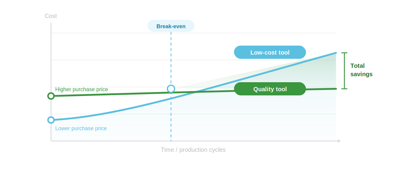
Total cost rather than purchase price

An experienced buyer does not evaluate the price of an injection molding tool in isolation. The relevant figure is the total cost over the tool’s service life, which includes:

  • The purchase price of the tool
  • Ongoing maintenance costs
  • Unit price of the produced items
  • Expected service life and number of cycles
  • The risk of unplanned downtime and repairs

An inexpensive tool that requires frequent maintenance, has a shorter service life, and produces a higher scrap rate is rarely the cheapest solution over time.

What factors influence the price in the early stages?

The decisions that have the greatest impact on the price are not made by the toolmaker. They are made by the person who designs the workpiece.

Part design, material selection, and tolerance requirements define the parameters of what a mold must be capable of. A DfM review early in the process is therefore not just good practice—it is the most effective way to ensure that the price reflects what is actually necessary, rather than paying for complexity that could have been avoided. Read more about how to do this in the article: From Idea to Finished Injection Molding Mold.

How to Prepare for a Price Discussion

To get an accurate and comparable quote, it’s helpful to have the following information ready:

  • 3D model and 2D drawings with tolerances
  • Material Requirements Specification
  • Expected annual volume and total lifetime volume
  • Surface and Finish Requirements
  • Documentation and validation requirements, including whether IQ, OQ, or PQ are required [INTERNAL LINK → Test Run, Commissioning, and Validation]
  • Desired delivery time

The more complete the information is, the more accurate the quote will be, and the easier it will be to compare quotes from different suppliers on a realistic basis.

Summary

The price of an injection molding mold is determined by the complexity of the part, the number of cavities, tolerance requirements, choice of steel, gate system, and size. There is no standard price because there is no such thing as a standard mold.

The key point is that the price is largely determined during the design phase. Decisions regarding workpiece geometry, material selection, and tolerances have a direct and measurable impact on the cost of a finished tool and its operating costs over time.

From concept to finished injection-molding tool

The development of an injection molding tool is not a linear process from design to production. It is a process in which decisions made early on have direct consequences for quality, cost, and delivery time—and in which close collaboration between the designer, toolmaker, and manufacturer is essential for a successful outcome.

Nevertheless, its complexity is often underestimated. An injection molding tool is not a standard component that can be specified without prior analysis. It is a precision tool that must be tailored to the specific part, the plastic material in question, and the production process in which it will be used.

This article walks you through the development process step by step—from the initial idea to a validated, production-ready tool.

Step 1: Subject Analysis and Requirements Specification

It all starts with the workpiece. Before a tool can be designed, there must be a clear understanding of what the workpiece is intended to do, under what conditions it will be used, and what requirements apply to tolerances, surface finish, and function.

It’s about answering a number of fundamental questions: What function must the part fulfill? Which dimensions and tolerances are critical? What loads must the part withstand, and what are the requirements for surface quality and finish? Finally, the expected production volume is crucial, as it directly influences the choice of the number of cavities and the steel grade.

The answers define the framework for everything that follows. A medical device application has different requirements than a technical cable conduit, and this is directly reflected in the tool’s design, choice of steel, and tolerance requirements.

Step 2: Selecting a Plastic Material

The choice of material is closely linked to the workpiece analysis, but deserves its own consideration. The plastic material not only affects the properties of the workpiece—it also influences how the tool should be designed and dimensioned.

Different materials have different requirements regarding injection pressure and process temperature, shrinkage and tolerances, surface treatment requirements in the mold cavity, as well as venting, cooling, and steel type. A material such as PEEK requires processing at high temperatures and places special demands on the steel and cooling system. Standard polypropylene is far more forgiving. Steel Grades for Injection Molding Tools – Selection of Tool Steel

Step 3: Design for Manufacturing

Once the part and material have been defined, the manufacturing process begins. It is crucial here that the part is designed not only for its function but also for the manufacturing process it will undergo.

Design for Manufacturing involves adapting the part’s geometry, wall thicknesses, draft angles, and transitions so that it can be produced efficiently and consistently in the injection molding process. Parts that are not optimized for production result in defects, scrap, and the need for post-processing.

Typical adjustments at this stage include introducing draft angles for easy ejection, optimizing wall thicknesses to avoid sink marks and stresses, moving parting lines to non-visible surfaces, and simplifying geometries that are difficult to manufacture in steel. Design for Manufacturing in Injection Molding Tools

Step 4: Design of the injection molding tool

Once the optimized blank design is in place, the actual tool design can begin. This is where all technical decisions come together in a design that can be manufactured and put into production.

The design determines the cavity layout (single-cavity vs. multi-cavity molds), the sizing of cooling channels, the ejection system, as well as the parting line and the directions of pull.

The choice of gate system is a key decision at this stage. In the vast majority of cases, a hot runner system is used, in which the molten plastic is kept liquid in heated channels all the way to the gate. This results in shorter cycle times, minimal material waste, and a cleaner part surface without gate marks. In special cases—typically involving very simple geometries, specific materials, or low-volume production—a cold runner system may be appropriate.

During this phase, mold filling analyses and flow simulations are typically performed to identify potential problems such as weld seams, air pockets, and uneven filling before steel is loaded into the machine.

Step 5: Making the Tool

Manufacturing is the physical process by which the design is transformed into steel. It is a process that requires high precision and involves several machining methods: CNC milling of mold cavities and cores, EDM for complex geometries and sharp internal corners, grinding to tight tolerances on mating surfaces and closing surfaces, as well as polishing and, finally, assembly and adjustment of all components.

Tolerances in an injection molding tool are typically in the hundredths-of-a-millimeter range. A manufacturing defect that is not detected early on may require the rework of entire sections and delay the entire project.

Step 6: Test Run, Break-in, and Validation

Before a tool is declared ready for production, it undergoes a controlled test run. During this test, the first workpieces are machined, and the results are systematically inspected against the specifications.

The test run determines whether the mold cavity is filled correctly, whether the tolerances are within specification, whether the surface is free of defects, and whether the cycle time is realistic. Any deviations are addressed during the run-in phase, when the mold is adjusted and optimized. Validation is the formal documentation that the mold and the process meet the requirements. Test runs, run-in, and validation of injection molds

How much does the entire program cost?

The development process from concept to validated tool is an investment that varies significantly depending on the complexity of the part, the number of cavities, the steel grade, and the requirements for tolerances and finish.

It is important to understand that the price of an injection mold cannot be assessed in isolation. Decisions made early in the process—regarding part design, material selection, and the number of cavities—have a direct impact on the total investment and on the operating costs over the mold’s service life. How much does an injection mold cost?

From a finished tool to long-term operation

Once a tool has been validated and put into production, the next phase begins: ensuring that the investment pays off over time. A well-designed tool is a good starting point, but it is maintenance that determines whether it can deliver the expected service life and quality.

The decisions made during the design and manufacturing phases directly affect how easy or difficult it is to maintain the mold during operation. Read more about how preventive maintenance of injection molds is carried out here.

Summary

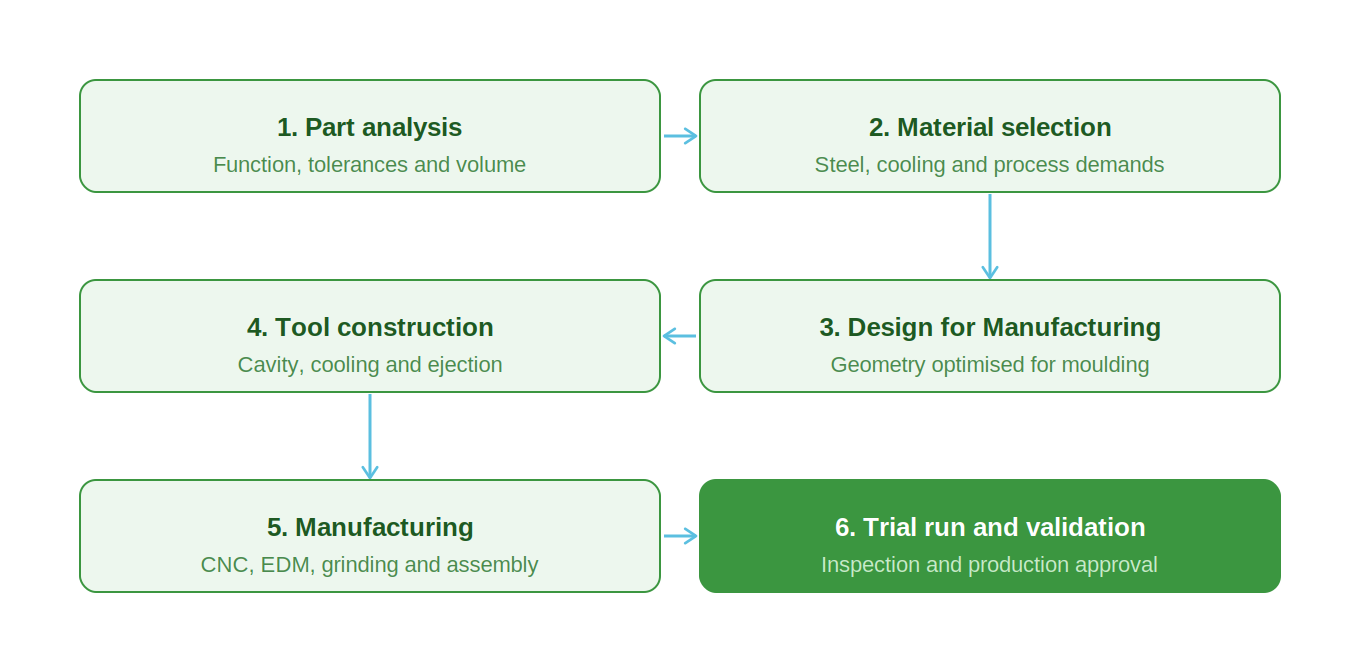
The development of an injection molding tool is a process consisting of six closely interrelated phases: part analysis, material selection, Design for Manufacturing, design, manufacturing, and validation. The quality of each phase depends on the quality of the preceding one.

The most costly errors in a tooling project rarely occur during manufacturing. They arise when decisions regarding workpiece design and material selection are made without sufficient technical analysis and are not discovered until the steel has been machined and time has been spent.

A well-structured development program reduces the risk of exactly that.

Design for Manufacturing in Injection Molding Tools

A part can be functionally correct and still be difficult to manufacture. This happens when the design is developed with a focus on the end function, but without sufficient consideration of how it will be manufactured using an injection-molding tool.

Design for Manufacturing, often abbreviated as DfM, is the discipline that bridges the gap between product design and production. It involves adapting the part’s geometry, wall thicknesses, and surfaces so that it can be manufactured consistently, efficiently, and within the specified tolerances.

In injection molding, DfM is particularly critical because errors in the design phase do more than just cause production problems. They manifest themselves in the finished product, and making changes once manufacturing has begun is costly and time-consuming. Read more here: From Idea to Finished Injection Molding Mold

What DfM Means in Injection Molding

Injection molding is a process with clear physical limitations. The plastic material is injected into a closed mold cavity under pressure, cools, and must then be ejected without damaging either the part or the mold.

For this to happen consistently and without errors, the part’s design must take into account how the material behaves during filling and cooling, and how the part can be physically removed from the mold. These requirements are translated into a series of specific design principles.

Exhaust Angles

One of the most fundamental prerequisites for successful injection molding is the presence of draft angles on all surfaces that are parallel to the direction of ejection.

Without draft angles, the part will stick to the mold cavity during ejection. This can cause surface damage, deformation, and, in the worst case, damage to the mold. Even an angle of 1 to 2 degrees is often sufficient to ensure clean ejection.

The requirements for relief angles vary depending on the surface finish and the material’s shrinkage. Workpieces with a matte or textured surface typically require larger relief angles than polished surfaces, because the surface texture increases friction against the steel surface.

Wall Thicknesses and Uniformity

Variations in wall thickness are one of the most common causes of quality issues in injection-molded parts. When a thicker section solidifies more slowly than the surrounding geometry, sink marks appear on the outer surface and internal stresses develop in the material.

The basic principle is uniform wall thickness throughout the entire workpiece. Transitions between thin and thick sections should be gradual and rounded rather than abrupt, so that the molten plastic can distribute evenly and cooling occurs in a controlled manner.

Recommended wall thicknesses vary from material to material. Engineering thermoplastics such as polyamide and polycarbonate have different optimal ranges than polypropylene and polyethylene. The choice of material and wall thicknesses are therefore decisions that are inextricably linked. Read more here: Steel Types for Injection Molding Tools – Selecting Tool Steel. 

Location of the dividing line

The parting line is the line where the two halves of the mold meet and close. Its location affects the part's appearance, functionality, and manufacturing costs.

A properly placed parting line is not visible on the critical surfaces of the part and allows for effective venting of the mold cavity. An improper placement requires complex core and gate solutions, which increase the mold’s complexity and cost. Read more here: How much does an injection mold cost?

In practice, the dividing line should be established early in the design process and treated not as a consequence of the geometry, but as an active design decision.

Cuts and Solutions

Interference fits are geometric features that prevent direct ejection in one direction. These can include internal grooves, external hook and snap connections, or through-holes perpendicular to the direction of ejection.

Undercuts require sliders or lifters in the tool—that is, moving mechanical components that are pulled to the side before the workpiece is ejected. This increases the tool’s complexity, cost, and maintenance requirements.

The DfM process is not about eliminating all undercuts, but about consciously assessing which ones are functionally necessary and which ones can be eliminated by redesigning the geometry without compromising the part’s function.

Ribs, reinforcements, and joints

Ribs are used to increase stiffness without increasing wall thickness. This is an effective approach, but ribs can cause indentations on the opposite side of the workpiece if they are incorrectly dimensioned.

As a rule of thumb, a rib should be 50 to 70 percent as thick as the adjacent wall. Ribs that are too thick lead to the same problems as wall thicknesses that are generally oversized.

Assembly holes are used for screw holes and mounting points. They should be designed with a center hole diameter that matches the selected screw type and with sufficient support geometry to prevent deformation during assembly.

Port Placement and Injection

The gate is the point where the molten plastic is injected into the mold cavity. Its location affects the filling pattern, the placement of any weld lines, and the surface quality of the finished part.

A nozzle positioned in the center of the workpiece typically produces the most uniform fill. A nozzle positioned at the edge can result in an oriented fill that leaves weld seams in critical locations or creates unwanted fiber orientation in reinforced materials.

The type of port—whether it is a point port, tunnel port, or film port—also affects the appearance of the workpiece and the need for post-processing. The port mark is visible on the workpiece and should be placed on non-visible surfaces whenever possible.

DfM in Practice

DfM is not a one-time review of a CAD design. It is an iterative process in which the designer, toolmaker, and manufacturer collaborate to ensure that the design can be manufactured as specified.

In practice, a DfM review typically identifies a handful of adjustments that, taken together, significantly reduce the risk of manufacturing problems. These adjustments are almost always less expensive to implement during the design phase than to correct once the steel has been loaded into the machine.

A part that has been DfM-optimized results in shorter cycle times, fewer rejects, and reduced tool maintenance requirements over time. This is directly reflected in the total production costs. Learn more about Preventive Maintenance

Summary

Design for Manufacturing in injection molding is about ensuring that the part’s geometry and the physical requirements of the production process are compatible with one another. Draft angles, wall thicknesses, parting lines, undercuts, and gate placement are all parameters that must be actively addressed during the design phase.

Parts that are not DfM-optimized are often produced with compromises in quality, cycle time, or maintenance requirements. Parts that are well-designed from the outset ensure more predictable and stable production throughout the tool’s service life.