Specialized tools for food packaging

Injection-molded packaging components for the food industry place demands on the injection mold that differ significantly from those of standard industrial applications. It’s not just about tolerances and cycle times—it’s about designing a mold that, from day one, supports the compliance journey that the packaging manufacturer is required to undertake.

The packaging industry is also in the midst of a structural transformation. The EU’s Packaging and Packaging Waste Regulation is pushing the market toward reusable solutions, and single-material plastic packaging is increasingly the answer. This places new and stricter demands on the molds used to produce this packaging—and this is precisely the intersection where Kellpo operates.

This article reviews the specific design and regulatory requirements that apply to injection molds for food packaging and explains why single-material specialization has become a competitive factor in its own right.

Who is responsible for compliance—and what does that mean in practice?

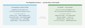
EU Regulation 10/2011 on plastic materials and articles intended to come into contact with food regulates the finished plastic product—the packaging—not the production equipment used to manufacture it. The responsibility for compliance lies with the company that produces the packaging: it must document that the finished plastic material complies with the regulation’s requirements and can provide a Declaration of Conformity.

The injection molding tool is not a food-contact material as defined by law. However, the mold is an essential prerequisite for the packaging manufacturer to be able to fulfill its obligations at all. A mold that produces inconsistent parts, varying wall thicknesses, or dimensional deviations makes it difficult for the customer to document a stable and reproducible process—and it is precisely this stability that forms the foundation of credible compliance documentation.

It is in this context that the choice of steel, surface finish, hot runner configuration, and cavity balance become compliance-relevant decisions—not because the mold itself is regulated, but because a well-designed mold is the technical foundation for the customer’s ability to produce consistent and verifiable results.

Single-material products and the next wave of packaging requirements

The EU’s Packaging and Packaging Waste Regulation (PPWR) sets ambitious targets for recyclability and requires that packaging be capable of being incorporated into a true material cycle. This regulatory driver is fundamentally changing the packaging industry’s design principles.

The industry’s response is increasingly to use mono-material packaging—packaging made from a single plastic material, typically PP or PE—rather than laminated, multi-layer structures that are difficult to separate and recycle. A cup, a lid, and a seal made from the same material can be recycled as a single fraction. A laminated structure with a barrier layer made of a different polymer system cannot.

For injection molding tools, the transition to mono-materials means that the mold can no longer compensate for variations in process parameters using the material system’s own properties. Single-material polypropylene or polyethylene places higher demands on mold precision, the uniformity of the cooling system, and the precision of gate placement, so that the part can achieve the dimensional stability and surface quality required in industrial packaging production. This is a design requirement that begins with the mold.

Steel Selection and Surface Treatment in the Food Industry

In conventional industrial tools, the choice of steel is based primarily on hardness, toughness, and machinability. In the food industry, corrosion resistance is added as a crucial fourth criterion.

The production environment in a packaging plant is demanding. Cleaning agents, temperature cycles, and materials containing fillers can, over time, corrode steel that has not been selected for this purpose. Corrosion in the mold cavity is unacceptable—partly because it compromises the surface of the part, and partly because corrosion can release particles that contaminate the part. Corrosion-resistant stainless steel grades are the standard choice for cavities in food-critical applications, and the specific steel grade is always verified in relation to the specific application and the customer’s requirements for their own process approval.

The surface treatment is at least as important as the choice of steel. A polished, smooth cavity surface free of cracks, gaps, or porosity promotes hygiene and facilitates cleaning—both of which are key factors in food production that must meet internal and external audit requirements. Steel grades for injection molding tools—selection of tool steel
Multi-cavity molds and cycle times

Food packaging is produced in very high volumes. A cap for a yogurt cup, a lid for a beverage, or a tray for fresh produce can be produced in the millions each week. This requires a high number of cavities and short cycle times.

An injection molding tool for high-volume production of packaging can have 16, 32, 64, or even more cavities, depending on the size of the part and the machine on which it is run. In single-material applications, balancing all cavities is particularly critical—all positions must receive identical melt, pressure, and cooling so that the parts can be kept within the tight dimensional tolerances characteristic of thin-walled parts. Single-cavity vs. multi-cavity molds

Cycle time is a key parameter. Thin-walled, single-material parts cool quickly but place high demands on mold filling and injection pressure because there is no multi-layer system to distribute the process energy. Optimizing the cooling system and hot runner layout is crucial for achieving the short cycle times that make packaging production profitable.

Hot-runner systems in food production

Hot-runner systems are standard in food packaging. This is due not only to the technical advantages they offer—shorter cycle times, minimal material waste, and a cleaner part surface—but also to the more closed and controllable production process they provide compared to a cold-runner system.

In a cold runner system, each shot produces a gate sprue of plastic material that must subsequently be separated and handled. In a single-material strategy, recycling gate sprues is technically possible, but it introduces additional handling steps and traceability requirements. A hot runner system eliminates the gate sprue and keeps the plastic material enclosed within the heated system all the way to the gate—a design that naturally aligns with a production philosophy based on minimal waste and maximum material control.

Documentation and validation as part of the customer's compliance

The compliance documentation for the finished plastic product requires that the packaging manufacturer be able to demonstrate a stable and reproducible injection molding process. This is where a new injection molding tool must be validated—not to meet requirements for the mold itself, but to establish the documentation basis the customer needs. Test runs, break-in, and validation of injection molding tools

Validation typically follows an IQ/OQ/PQ structure, in which it is documented that the equipment is correctly installed, that the process is under control within defined parameters, and that the resulting product consistently meets the specification. In the context of packaging, this documentation process is closely linked to the customer’s internal approval requirements and any requirements from food regulatory authorities or major buyers in the supply chain.

Maintenance and Service Life in Packaging Production

A high number of cavities and short cycle times mean that an injection molding mold used for packaging production accumulates shots very quickly. A 32-cavity mold operating at a 5-second cycle time reaches one million shots in less than 44 hours. This places high demands on the maintenance strategy.

Preventive maintenance is not an option but a necessity in packaging production. An unplanned stoppage on a packaging line has direct consequences for downstream production and delivery reliability. Preventive maintenance

The type of steel, surface treatment, and build quality directly affect how often maintenance is required and what it entails. A solid foundation laid during the design phase provides the best conditions for a long service life without unplanned downtime. What determines the service life of an injection molding tool?

Summary

An injection molding tool for food packaging is not merely a production tool—it is the foundation of the packaging manufacturer’s ability to demonstrate a stable, compliant, and reproducible process. The responsibility for ensuring the finished product’s compliance rests with the packaging manufacturer, but the mold’s quality, precision, and design are essential for fulfilling that responsibility.

As the packaging industry shifts toward single-material solutions driven by the PPWR and recyclability requirements, the design requirements for molds are increasing. Single-material packaging made of PP or PE requires higher mold precision, tighter cavity balancing, and more controlled thermal management than traditional multi-layer designs. This technical development gives specialized mold manufacturers a central role in the packaging industry’s green transition.

Prototype vs. Production Molds

An injection molding mold is a major investment. The question isn’t always which mold to build—but in what order, and on what basis.

A prototype mold is a learning tool. It is used to clarify what has not yet been clarified: whether the part design works in practice, whether the plastic material behaves as expected, and whether the process is controllable. A production tool is the answer once those questions have been answered.

This article explains the difference between the two types of molds, when each is the right choice, and what bridge tooling entails as an intermediate step.

What is a prototype mold—and what isn't it?

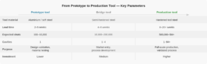
A prototype mold produces a limited number of parts for validation and testing. It is made of aluminum or a softer steel material, which results in a shorter manufacturing time and a lower cost than a fully hardened production mold—but, on the other hand, it has a shorter service life and lower tolerance capabilities.

The prototype mold can validate basic geometry, surface quality, and part assembly. It can be used to test how a plastic material behaves within the specific geometry and to identify design issues that are not apparent in simulations.

What it cannot do: document the stable, reproducible process required for formal process validation. The material and tolerances of a prototype mold do not reflect those of the final production tool, and parts produced in a prototype mold are not, strictly speaking, produced under production conditions. In regulated industries—such as medical devices and food-contact materials—validation data must be derived from the actual production tool.

Test runs, break-in, and validation of injection molding tools

When is a prototype mold the right choice?

The prototype approach is useful when there are specific, unresolved questions that only physical objects can answer.

The part design is unclear: the geometry has not been critically reviewed in relation to the injection molding process, and there are real risks that draft angles, wall thickness ratios, or mating surfaces will not function as expected. Detecting these issues in aluminum is far less expensive than detecting them in hardened steel.

The plastic material is unpredictable: shrinkage, deformation, and processability in the specific geometry differ from the values listed in the data sheet, and only a physical test run can confirm whether the material and the part are compatible. Design for Manufacturing in injection molding tools

The market potential is unclear: a physical product is needed for user testing, presentations, or in-store testing before investing in full production capacity. Prototyping provides samples for these purposes at a fraction of the cost of a production mold.

Aluminum and milder steels vs. hardened structural steel

Aluminum is easy to machine. This results in lead times of two to five weeks and low machining costs. On the other hand, aluminum has much lower hardness and wear resistance than hardened steel and is unsuitable for more than a relatively small number of shots—enough for validation, but insufficient for mass production.

The mold is manufactured from hardened steel selected based on the workpiece’s tolerance requirements, surface finish requirements, and the plastic material to be processed. The choice of steel is a technical decision that balances hardness, toughness, corrosion resistance, and machinability. Steel Types for Injection Molding Tools – Selection of Tool Steel

Parts from a prototype mold and parts from a production mold are not identical, even though they are made from the same plastic material and have the same geometry. Surface roughness, dimensional tolerances, and shrinkage behavior differ because the steel surface, mold temperature, and process variability are different. This is a limitation that is crucial to understand in applications with tight tolerance requirements.


Bridge tooling – the intermediate station

A bridge tool is designed to produce a larger number of parts than a prototype mold allows, but with a shorter lead time and lower investment than the final production tool. It is made of semi-hardened steel and is typically rated for 10,000 to 200,000 shots.

Bridge tooling is used when there is a specific time constraint on the start of production—for example, a market launch window that cannot wait for the final production tool. It is also used to build up inventory capacity before the start of full production, or to gain process experience that can inform the design of the final tool.

The bridge solution is not always the right choice. If the process is well-documented and the subject matter has been validated, the additional investment is difficult to justify. However, in projects with tight timelines and an unclear process foundation, bridge tooling reduces the risk that the final production tool will be designed on an inadequate basis.

When should you go directly to the production tool?

The direct jump is the right choice when three conditions are met.

The part design has been validated: the geometry has been reviewed in relation to the injection molding process, draft angles and wall thicknesses have been optimized, and there are no geometric ambiguities that require physical testing. From concept to finished injection mold

The plastic material is well known: it has been processed under similar conditions in the past, and its shrinkage and processing parameters have been documented. There are no material-related risks that require clarification through test specimens.

The business case is solid: the production volume has been determined, and there is no need for market validation by producing test parts before mass production begins. How much does an injection molding tool cost?

If one of the three conditions is not met, a prototype phase should be considered. The investment in a prototype mold is small compared to the cost of discovering fundamental problems in a fully hardened production mold.

Number of cavities in prototype and production molds

The prototype mold is almost always a single-cavity tool. The purpose is validation, not volume production, and a single-cavity tool provides the clearest process-related information about the part’s behavior. Multi-cavity molds are production tools—they require that the geometry, material, and process be defined, because balancing and optimizing multiple cavities is an investment in itself that does not make sense to undertake on an uncertain basis. Single-cavity vs. multi-cavity molds

The transition from a prototype mold to a multi-cavity production mold is not simply a scaling up of the prototype. It is a new design based on the insights gained during the prototyping process.

Summary

The prototype mold is useful when there are specific unresolved questions regarding part design, plastic material, or market feasibility—questions that can only be answered using physical parts. The production mold is the right starting point once those questions have been answered and the prerequisites have been documented.

Bridge tooling solves the specific problem of time constraints: it provides parts for market launch or inventory build-up while the final production tool is being manufactured. For projects without such time constraints, bridge tooling is rarely necessary.

The most costly scenario in any mold-making project is discovering a fundamental design problem in a fully hardened production mold. A well-considered decision regarding whether to proceed with prototyping or go directly to production is the most effective way to avoid this.

Modular injection molding tools

A conventional injection molding mold is designed for a single part. If the same part is to be produced in three sizes or four variants, this requires three or four separate molds—each requiring a full investment, full production time, and a full maintenance program.

A modular injection molding tool solves this problem by separating the common elements from the variable ones. The mold base—including the hot runner, cooling, ejection system, and control system—is standard and reused across all variants. Only the inserts, which define the part’s geometry, are interchangeable. A new variant requires a new insert, not a new mold.

It is a design principle that significantly changes the investment logic for product families—but it also places greater demands on design precision and coordination than a conventional single-cavity mold.

The Principle Behind Modular Tools

The basic structure of a modular injection molding tool is a standardized mold frame that contains all the elements common to all variants: the hot runner system, the cooling circuit, the ejection system, and the guide rails. The frame is designed to accommodate interchangeable inserts that define the cavity geometry.

An insert is the part of the mold that determines the shape, surface, and dimensions of the part. By changing the insert in the same mold base, a new variant is produced—using the same machine, the same hot runner system, and the same cooling and ejection configuration. The mold base is a one-time investment. The inserts are the variable component.

The system requires that all designs be created within the framework’s defined limits and interfaces. This means that the geometric freedoms available in a dedicated conventional tool are not always available in a modular system. Flexibility is present—but within defined limits.

When is a modular injection molding tool the right choice?

Modular tooling makes the most sense when two conditions are met: there is a defined product family with multiple variants, and the variants share a sufficient basic geometric structure to be produced within the same framework.

The classic example is packaging in the same series but in different sizes—a container available in 250 ml, 500 ml, and 1000 ml with the same cross-sectional geometry and the same locking system. Here, the mold frame is identical for all three sizes; only the cavity height and insert geometry vary. A modular solution significantly reduces the total investment and makes it possible to add new sizes to the series without having to start a new, complete mold tooling project.

Modular tooling is also useful in product development phases where the workpiece undergoes iterative changes: instead of ordering a new, complete tool for each design revision, a new insert is ordered for the existing frame. This significantly reduces both the cost and the lead time per iteration.

Finally, modular systems are used in situations where the production of multiple variants must be handled flexibly on a single machine—for example, in packaging production involving short runs and frequent changeovers. Specialized tools for food packaging


Design Principles – What Is Standardized and What Is Customized

The mold frame standardizes all elements that are independent of the part’s specific geometry. The hot runner system is designed to accommodate all planned inserts and is permanently mounted in the frame. The cooling circuit is routed through the frame and connected to the inserts via standardized couplings. The ejection system and guide rails are fixed to the frame and designed to handle the force and precision required by all inserts.

The inserts are designed within the frame’s specified interfaces: dimensions, mating elements, connection points for cooling and the hot runner, as well as ejector positions, are all defined by the frame and cannot be deviated from without rendering the insert incompatible. This places high demands on the coordination between the frame design and the insert design—and on the precision with which the inserts are machined.

The selection of steel for inserts follows the same principles as for conventional cavities: the blank geometry, the plastic material, and the requirements for surface finish and service life determine which steel is chosen. Steel grades for injection molding tools—selection of tool steel

Tolerances and Fits – The Critical Interface

The weakest point in any modular system is the mating between the insert and the frame. This is where two separate machined components meet, and any inaccuracy in this mating directly affects the quality of the workpiece: mating lines, dimensional deviations, and leaks of molten metal or coolant are all consequences of mates that do not meet the tolerance.

The tolerance requirements for the mating between the insert and the frame are typically tighter than for most other components in an injection molding tool. The mating must function under the thermal and mechanical stresses that arise during production—including thermal expansion, which can alter the geometry of the mating depending on the operating temperature. A modular system that is properly designed and machined handles this without any problems. A system with insufficient precision causes problems that are more difficult to diagnose than in a conventional mold, precisely because the variable is the interface and not the cavity in isolation.

Hot Runners in Modular Solutions

In the vast majority of modular solutions, the hot runner system is frame-mounted and designed to accommodate all planned inserts. This means that the gate geometry, gate location, and nozzle type are defined by the frame and must be compatible with all inserts in the system. This is a key design limitation: an insert that requires a gate location or type that deviates from the frame’s standard cannot be integrated without modifying the hot runner system—or designing a new frame.

In contrast, the hot-runner system in a modular solution eliminates the gate sprue that would otherwise occur in cold-runner production and ensures that switching from one insert to another can be done without changing the hot-runner configuration. This results in short changeover times and a production process that is consistent across all variants.

Investment and Time Savings

The primary economic benefit of a modular system is that the initial investment is spread across all variants in the system. The more variants produced over the system’s lifetime, the lower the effective cost per variant. For a product family with four to eight variants, the savings are often significant compared to four to eight separate conventional molds. How much does an injection molding tool cost?

The time savings on new inserts are also significant. Once the frame has been designed and tested, the production time for a new insert is considerably shorter than for a completely new tool. This reduces the time to market for new variants and provides a real product development advantage in markets with frequent product updates.

Maintenance is simplified because the framework is shared: servicing of the hot runner system, cooling circuit, and ejector system is performed once and covers all inserts. The inserts are maintained independently, but the common frame reduces the overall maintenance burden compared to an equivalent number of conventional molds. Preventive maintenance

Limitations – When a Modular Approach Doesn't Make Sense

A modular system is not universally superior to conventional dedicated tools. It requires more advance planning than a conventional single-mold tool: the frame must be designed with all planned inserts in mind from day one, because subsequent changes to the frame’s interfaces are costly.

Workpieces with very different geometries that impose conflicting requirements on gate placement, cooling, or ejectors are difficult to integrate into the same modular system. In such cases, separate conventional tools are the more flexible solution.

For single-unit production runs without planned variants, the additional design effort required to establish a modular system is rarely cost-effective. A dedicated single-cavity mold is simpler, faster to design, and fully tailored to the specific requirements of the part. Single-cavity vs. multi-cavity molds

Summary

A modular injection molding tool is the solution when a product family with several geometrically related variants needs to be produced flexibly and with a lower overall investment than a corresponding number of conventional tools. The principle is simple: standardize the common elements and make the variable elements interchangeable.

Implementation requires precision in design and machining—particularly at the interface between the insert and the frame—as well as advance planning of all variants before the frame is constructed. A properly established modular system results in a shorter time-to-market for new variants, a lower total investment, and a simplified maintenance structure. A system designed without sufficient prior coordination leads to mating issues and geometric constraints that are costly to correct later on.

From concept to finished injection-molding tool

Single-cavity vs. multi-cavity molds

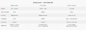
Choosing the number of cavities is one of the most significant decisions in an injection molding tooling project. It affects the size of the investment, the unit cost in production, the complexity of the mold, and the requirements placed on the machine, the process, and maintenance. Yet the decision is not always made based on sufficient analysis—and the consequences of a wrong choice only become apparent once the mold is in operation.

A single-cavity mold produces one part per shot. A multi-cavity mold produces two, four, sixteen, or even more identical parts in the same cycle. The difference sounds simple, but the design and process implications are significant—and the optimal choice depends on factors that extend far beyond the immediate production needs.

This article reviews the parameters that determine the number of cavities, the design requirements that result from this, and the trade-offs that should inform the decision.

What determines the number of cavities?

The starting point is always the production volume. How many parts need to be produced—per year, per week, per shift? The required volume, when compared with the desired cycle time and the available machine capacity, provides a mathematical basis for determining how many cavities are needed.

However, production volume is only one variable. The size and geometry of the part set limits on how many cavities can be placed in a mold of a given size—and the machine’s clamping force and injection capacity set limits on how much plastic material can be processed per shot. In practice, a large, complex part with tight tolerance requirements can only be produced using a single-cavity mold, even at high volumes, because the mold simply cannot be scaled up without losing control of the process.

The investment horizon is also a factor. A multi-cavity mold is more expensive to design and manufacture than a single-cavity mold for the same part. If the production volume is uncertain, or if the part is expected to change, it may make sense to start with fewer cavities and expand later—if the design allows for it. How much does an injection molding tool cost?

The single-cavity mold—when does it make sense?

The single-cavity mold is not a compromise solution for low-volume production. In many cases, it is the right choice for precisely the reasons that make multi-cavity molds appealing: simplicity, control, and focus.

Complex geometries with tight tolerances, undercut solutions, clamping operations, or demanding surface finish requirements are much easier to master in a single-cavity mold, where the designer can focus all resources on a single mold cavity. Troubleshooting and adjustment are correspondingly easier—there are no other cavities to compare with, and each shot represents the full complexity of the mold.

The single-cavity mold is also the standard choice for prototype and pre-production runs, where the process is still under development and the part’s final geometry may not yet have been determined. Investing in a multi-cavity mold before the design has been validated is a risk that most manufacturers rightly avoid. Prototype vs. Production Molds

Technical components for medical devices, precision parts for electronics, and specialty components for industrial applications are often manufactured using single-cavity molds—even for production volumes that, in theory, could justify the use of multi-cavity molds—because process control and documentation reliability take precedence over unit-cost optimization.

The Multi-Cavity Mold – Advantages and Prerequisites

Multi-cavity molds are the answer when high volumes and low unit costs are the primary goals. By producing four, eight, or sixteen parts per shot, the effective cycle time per part is reduced accordingly—without machine costs increasing proportionally. This is the fundamental principle behind all high-volume production in injection molding.

However, multi-cavity molds present challenges that do not exist to the same extent with single-cavity molds. The most important of these is balancing: all cavities must receive an identical amount of molten plastic, identical pressure, and identical cooling—at exactly the same moment and in exactly the same quantities. If one cavity fills faster than the others, pressure variations occur, resulting in dimensional deviations, overfilled parts, or incomplete fills. Specialized molds for food packaging

The more cavities there are, the greater the demand for precision in design, machining, and process setup. A 32-cavity mold requires that all 32 cavities be machined within the same tolerances and connected to the hot runner system with exactly the same hydraulic resistance in all branches.

Cavity Balancing—The Essential Prerequisite

Balancing a multi-cavity mold involves ensuring that the molten plastic and process pressure are distributed equally to all cavities. This is achieved primarily in two ways: geometric balancing through the layout of the runner system, and thermal balancing through the design of the cooling system.

In a geometrically balanced runner system, all branches from the central injection point to the cavity are of identical length and cross-section—the classic H-tree configuration. This ensures that the pressure drops are equal in all branches and that the melt reaches all cavities simultaneously. In a hot runner system, the same result is achieved through precise sizing of the manifold and the nozzle system.

Thermal balancing ensures that all cavities cool at the same rate and to the same temperature. Inconsistent cooling causes dimensional variations and can result in parts from certain positions consistently deviating from specifications—a problem that can be difficult to isolate, precisely because the variation is systematic rather than random.

In practice, perfect balancing is an engineering goal that is approached but rarely achieved perfectly. The remaining variations are addressed during the break-in phase, when process parameters are adjusted to compensate for the natural asymmetries that arise in any system of a certain complexity.

Family Tools – Same Format, Different Topics

A variation of the multi-cavity concept is the family mold, in which a single mold contains cavities for several different parts that belong to the same product family. Typically, these are parts that are assembled together and are always produced in the same ratio.

The family mold may seem attractive because it reduces the number of molds and thus the total investment. However, it introduces a significant balancing challenge: parts of different sizes and geometries require different injection times, different pressures, and different cooling. Optimizing all parameters for all cavities simultaneously is a design challenge and typically compromises the process for at least one of the parts. The family mold is therefore best suited for parts that are closely related in size and material volume.

From Cavity Design to Construction

The number of cavities is not merely a production parameter—it is a design framework that determines everything from mold size and steel mass to the injection system, cooling circuit, and ejector configuration. A change in the number of cavities after design work has begun is rarely a simple scaling exercise; it may require a fundamentally new design. The decision should therefore be made early in the process and with a clear understanding of the long-term production requirements. From concept to finished injection mold

Once the number of cavities has been determined, it largely dictates which machine the mold will be used on, which hot-runner platform is appropriate, and what tolerance requirements apply to the machining process. This is a decision that has implications throughout the entire project lifecycle.

Summary

The choice between single-cavity and multi-cavity molds is not a matter of ambition, but of analysis. Production volume, part complexity, tolerance requirements, investment horizon, and machine capacity must all be weighed—and the correct answer is the one that optimizes the overall economics over the mold’s service life, not just the investment on day one.

The single-cavity mold provides maximum process control and is the right choice for complex parts, low- to medium-volume production, and situations where the process has not yet been fully validated. The multi-cavity mold offers lower unit costs at high volumes, but requires careful balancing of melt, pressure, and cooling to ensure that all cavities produce identical parts. The more cavities there are, the greater the demands on design precision and commissioning expertise.